The fear of being obsolete is real, but the solution isn’t to abandon old skills—it’s to reframe them as a strategic advantage in a digital world.
- Manual drafting builds “digital intuition,” making you a faster, more accurate CAD user by fundamentally understanding 3D space.
- Hand-calculation and sketching act as critical risk-mitigation tools, preventing costly errors in digital models that software alone can miss.
Recommendation: Focus on certifications that blend digital proficiency (BIM/Revit) with your foundational manual skills to command a premium salary and position yourself as an indispensable hybrid professional.
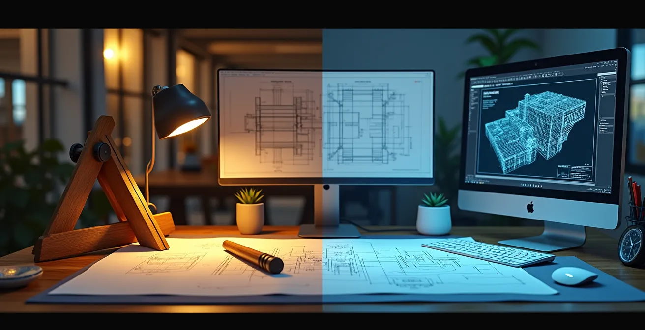
In offices once filled with the scent of paper and graphite, the quiet hum of servers now dominates. For the seasoned technician whose hands instinctively know the heft of a scale ruler, or the student just mastering the art of the T-square, a persistent question looms: in an era dominated by CAD, is manual drafting an obsolete relic or a hidden superpower? The common refrain is that to stay relevant, one must master software like AutoCAD or Revit, leaving hand-drawing skills to gather dust alongside the drafting table.
This advice, while well-intentioned, misses a crucial strategic point. The debate isn’t about choosing ‘manual OR digital,’ but understanding how to leverage ‘manual FOR digital.’ What if your deep-seated knowledge of projection, line weight, and spatial relationships is the very thing that transforms you from a competent software operator into an elite, indispensable engineering professional? The true value of hand-drawing today lies not in producing final documents, but in building a cognitive bridge that enhances digital proficiency, mitigates costly project risks, and fosters a deeper, more intuitive understanding of design.
This article moves beyond the surface-level debate to provide a strategic roadmap for technicians and students. We will explore exactly how these foundational skills translate into faster 3D modeling, superior error detection, and ultimately, a more valuable and hireable profile in the modern engineering landscape. By reframing your classic skills as a strategic asset, you can confidently navigate the career shift from analog practitioner to high-value digital expert.
text
To navigate this transition effectively, it’s essential to understand how each aspect of manual drafting directly enhances digital workflows. The following sections break down the specific, hireable advantages that a foundation in traditional techniques provides in a software-driven industry.
Summary: Manual Drafting Skills in a Digital Engineering World
- Why understanding descriptive geometry helps you model faster in 3D software?
- How to interpret complex architectural symbols when the tablet battery dies?
- Building Information Modeling vs. Flat CAD: Which certification boosts salary more?
- The unit conversion mistake that can cost a construction project millions
- How to redline a digital drawing effectively to communicate changes to the team?
- The weight calculation mistake that cracks the slab under your sculpture rack
- Raster vs. Vector: Which file type should you send for a logo embroidery?
- How to Reduce Foundry Costs Without Sacrificing the Quality of the Cast?
Why understanding descriptive geometry helps you model faster in 3D software?
Descriptive geometry is the grammar of 3D space. Before a single line is clicked in CAD, an engineer who has mastered manual orthographic and isometric drawing has already built a powerful mental framework. This is the cognitive bridge between a 2D screen and a 3D object. Instead of treating the software as a magic box, they understand the underlying principles of projection, section views, and auxiliary planes. This allows them to anticipate how a model will behave, troubleshoot complex geometries, and construct forms with fewer steps and less trial-and-error.
This isn’t just a theoretical benefit; it has a measurable impact on efficiency. The ability to mentally rotate an object, visualize its cross-sections, and predict the curves of intersection before modeling is a massive accelerator. It’s the difference between blindly following software prompts and strategically directing the tool with foreknowledge.
Case Study: MIT Engineering Design Course: From Manual Sketching to Digital Precision
MIT’s Engineering Design Instructional Computer System provides compelling evidence for this synergy. Studies within the program demonstrate that students who first master manual orthographic and isometric drawing techniques are able to complete complex 3D CAD models 40% faster than those who start directly with the software. This advantage is particularly pronounced when dealing with intricate assemblies that require the creation and interpretation of multiple section views, proving that a manual foundation is a direct catalyst for digital speed and precision.
Ultimately, a drafter fluent in descriptive geometry doesn’t just use CAD; they speak its native language. This fluency allows for more intuitive, efficient, and sophisticated modeling, making them a far more productive member of any design team.
How to interpret complex architectural symbols when the tablet battery dies?
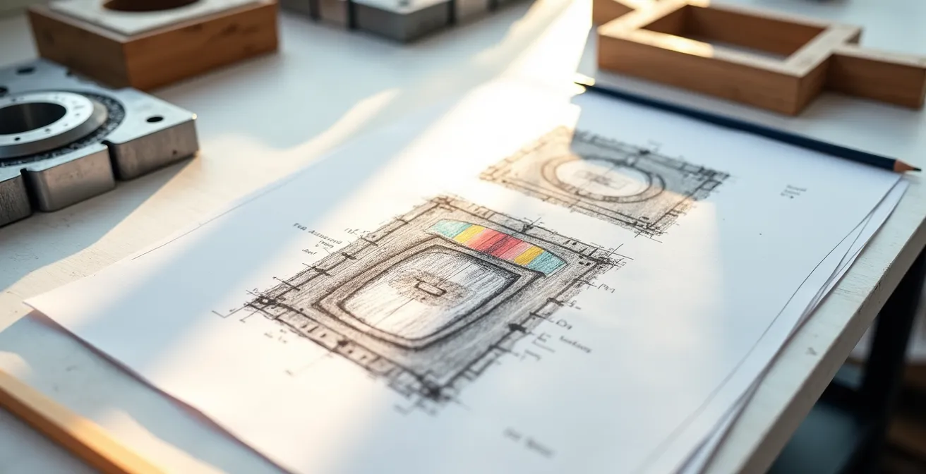
Imagine being on a construction site for a renovation project. Your tablet, holding all the digital plans, dies. The only reference is a set of original, decades-old blueprints. Suddenly, the ability to read non-standard, hand-drawn symbols is not a nostalgic skill but a critical project-saving one. This scenario is far from rare; heritage conservation studies reveal that 73% of renovation projects involve pre-1990s blueprints featuring symbols that modern software libraries don’t recognize. Without the ability to perform this “analog validation,” work can grind to a halt or, worse, proceed based on incorrect assumptions.
Interpreting these legacy drawings requires a specific skillset honed by manual drafting experience. It involves recognizing the drafting conventions of a particular era, understanding how line weights communicate material and structural hierarchy, and using contextual clues from the entire drawing set to decipher an unfamiliar symbol. This is a form of design forensics that pure CAD users may lack.

As the image above illustrates, this process is often meticulous, relying on a deep understanding of drawing logic rather than a simple digital legend. A drafter trained in manual techniques can cross-reference material callouts, identify patterns across sheets, and even redraw a detail by hand to internalize its construction logic. This ability to bridge the gap between historical and modern documentation is an invaluable risk mitigation tool, preventing costly misinterpretations and ensuring the integrity of the project.
Building Information Modeling vs. Flat CAD: Which certification boosts salary more?
For a professional navigating a career shift, choosing the right certification is a critical strategic decision. While a standard AutoCAD certification demonstrates proficiency in 2D drafting, the industry’s trajectory points decisively towards Building Information Modeling (BIM). BIM is not just 3D CAD; it’s a process that embeds crucial data (cost, scheduling, materials) directly into the model. Consequently, certifications in BIM software like Revit are in significantly higher demand and command a greater salary premium.
However, the greatest value lies not in simply replacing one skill with another, but in combining them. A professional who can leverage their foundational hand-drawing knowledge within a BIM environment is the most valuable of all. They can intuitively spot when a data-rich model is physically implausible, using their “digital intuition” to validate the software’s output against the laws of physics and construction logic.
An analysis of industry salary trends reveals a clear hierarchy, where a hybrid skillset offers the most significant financial return. As a report from Autodesk highlights, the ability to validate complex digital models is a premium skill.
| Certification Type | Average Salary Increase | Time to Proficiency | Industry Demand |
|---|---|---|---|
| AutoCAD Certified Professional | 15-20% | 6-12 months | High in 2D drafting roles |
| Revit/BIM Specialist | 25-35% | 12-18 months | Very high in AEC |
| Hybrid (CAD + BIM + Hand Skills) | 40-50% | 24+ months | Premium for leadership roles |
Professionals who can validate a BIM model’s data against first-principles and physical reality command higher salaries
– Autodesk Industry Report, CAD Software Solutions Guide 2024
The data is clear: while a move to BIM is a smart career choice, true market leadership comes from being the professional who can bridge the gap between the digital model and the real world—a skill deeply rooted in the principles of manual drafting.
The unit conversion mistake that can cost a construction project millions
In 1999, NASA’s $125 million Mars Climate Orbiter was lost because one engineering team used metric units while another used imperial units. This catastrophic failure, known as the “Mars Climate Orbiter Effect,” serves as a powerful cautionary tale for the construction industry. A similar error in a digital drawing—a misplaced decimal point or a default unit setting that goes unchecked—can lead to misfabricated steel beams, incorrectly poured foundations, and budget overruns costing millions. Software is incredibly precise, but it is not infallible; it will execute a flawed instruction with the same efficiency as a correct one.
This is where the drafter with manual experience provides a critical layer of risk mitigation. Years of working with physical scale rulers and performing manual calculations build an intuitive “feel” for dimensions. This is the essence of digital intuition—the ability to look at a dimension on a screen and immediately recognize that “something feels wrong.” A CAD-only user, accustomed to trusting the software’s output implicitly, may completely miss an anomaly that a seasoned manual drafter would flag instinctively.
Implementing manual checks as a formal part of the digital workflow is not a step backward; it is a professional quality assurance protocol. By forcing a moment of “analog validation” before releasing files for construction, teams can catch errors that could otherwise prove disastrous.
Your 5-Step Unit Conversion Sanity Check
- Point of Contact Review: Print out drawings with key dimensions and verify them against a physical scale ruler before any construction release.
- Dual-Unit Implementation: Implement dual-unit dimensioning (e.g., mm [in]) on all critical structural elements to provide an immediate cross-reference.
- Manual Checkpoint Establishment: Mandate manual calculation checkpoints for all load-bearing specifications to ensure they align with the digital model.
- Sanity Range Creation: Define and document acceptable dimension ‘sanity ranges’ based on standard material sizes (e.g., a steel I-beam is unlikely to be 10 meters wide).
- Large-Scale Verification: Require mandatory hand-calculation verification for any single dimension exceeding a project-defined threshold, such as 10 meters.
This simple protocol transforms a potential weakness of digital workflows into a strength by embedding human intuition and experience as a final, critical failsafe.
How to redline a digital drawing effectively to communicate changes to the team?
In the age of digital collaboration, “redlining”—the process of marking up drawings to indicate changes—has moved from red pens on vellum to styluses on screens. However, the most effective digital redlining borrows its philosophy directly from manual drafting. The goal is not just to state a correction, but to communicate the *intent* behind the change clearly and collaboratively. A hard, geometric correction made with precise CAD lines can feel prescriptive and shut down discussion. In contrast, a soft, hand-sketched annotation invites dialogue and signals a conceptual suggestion rather than a final command.
This distinction is crucial for team dynamics and design development. Using a stylus to sketch a cloud bubble around an area with a handwritten question encourages feedback. Drawing a rough, freehand alternative for a detail communicates design intent more fluidly than a rigid, new geometric construction. This approach leverages the human element of sketching to make the digital workflow more collaborative and less confrontational.

Furthermore, classic organizational techniques from the era of overlay drafting are more relevant than ever. Creating separate, color-coded layers for different disciplines (e.g., red for Architectural, blue for Structural, green for MEP) within a digital file mirrors the clarity of physical overlays. It prevents a chaotic mess of comments and ensures that each team member can easily filter for the markups relevant to them. Effective redlining is a communication skill, and the techniques refined over decades of manual practice provide a robust framework for making digital collaboration more efficient and human-centered.
The weight calculation mistake that cracks the slab under your sculpture rack
Consider a simple task: installing a heavy steel rack in a gallery to hold bronze sculptures. A junior designer, relying solely on a CAD program’s material properties, models the rack and its fasteners. The software confirms the rack itself is strong enough. However, nobody performed a “back-of-the-envelope” manual calculation of the total weight—sculptures included—and its point load on the concrete slab. The result: a cracked slab and a costly, dangerous failure. This is a classic example of where digital intuition, built from manual practice, provides an essential safeguard.
A drafter with manual experience develops an innate understanding of load paths through the practice of line weight visualization. In hand drawing, heavier lines are used to represent elements under greater stress, forcing the drafter to constantly think about how forces travel through a structure. This mental exercise is a powerful form of error checking. In fact, structural engineering studies show that manual drafters detect 89% of load path errors through this intuitive visualization process alone, long before a single calculation is run in a finite element analysis (FEA) program.
Performing a quick, simplified hand calculation is a crucial step of analog validation. It isn’t meant to replace detailed software analysis but to serve as a sanity check that confirms the software’s results are in the right ballpark. This simple verification process can be formalized with a few key steps:
- Calculate the total material volume using basic geometric shapes (cubes, cylinders).
- Multiply the estimated volume by the material’s density for a rough weight estimation.
- Sketch a simple free-body diagram to visualize how forces are distributed.
- Identify potential stress concentration points through visual analysis of the sketch.
- Verify the final design with at least a 20% safety margin before committing to FEA modeling or fabrication.
Raster vs. Vector: Which file type should you send for a logo embroidery?
The distinction between raster and vector file types is a fundamental concept in digital design, but its practical importance is deeply rooted in the principles of technical drawing. A raster file (like a PNG or JPG) is a map of pixels, similar to a photograph. A vector file (like an SVG or AI) is a set of mathematical instructions, similar to a drafting compass and ruler creating a perfect arc. For a manufacturing process like embroidery, where a machine follows a path to create stitches, a vector file is non-negotiable. Sending a raster logo will result in a blurry, unprofessional mess, as the machine has no clear path to follow.
This technical requirement mirrors the discipline of manual drafting. A technical pen forces a designer to think in terms of clear lines, paths, and defined shapes. There is no “blur” or “smudge” tool. This mindset directly translates to creating effective vector graphics. The most successful workflows often begin with a hand sketch to capture an authentic, creative feel, which is then carefully traced into a clean vector format. This hybrid approach preserves the character of the original idea while meeting the strict technical demands of production.
Case Study: From Hand Sketch to Vector Embroidery Success
Many design firms report that logos and graphics which originate as hand sketches, and are then meticulously traced into a vector format, retain an “authentic character” that is often lost in purely digital creations. This process ensures the design not only feels genuine but also adheres to the practical constraints of manufacturing, such as embroidery stitch count limitations. This workflow parallels how the physical limitations of technical pens and other drafting tools historically forced a clarity and economy of line that resulted in stronger, more effective designs.
Understanding this distinction is critical for any engineer or designer who needs to deliver files for production. The table below outlines the core differences and their implications for manufacturing.
| File Type | Best Use Case | Embroidery Suitability | File Size |
|---|---|---|---|
| Vector (SVG/AI) | Final production files | Excellent – scalable paths | Small (KB) |
| Raster (PNG/TIFF) | Initial concept presentation | Poor – requires conversion | Large (MB) |
Key Takeaways
- Manual skills are not obsolete, they are a cognitive accelerator: Hand-drawing builds spatial reasoning that makes you a faster and more intuitive CAD operator.
- Hand-drawing is a risk management tool: Manual checks for units, scale, and load paths prevent catastrophic and costly errors that software alone can miss.
- A hybrid skillset commands a premium: Professionals who can validate digital models (BIM/CAD) with first-principle knowledge rooted in manual drafting are the most valuable and highest-paid.
How to Reduce Foundry Costs Without Sacrificing the Quality of the Cast?
For any project involving cast metal parts, design decisions have a direct and significant impact on foundry costs. Complex molds, unnecessary material, and poor cooling characteristics can dramatically inflate production expenses. Here again, the principles of manual drafting provide a powerful toolkit for designing for manufacturability (DFM) and achieving cost efficiency without compromising the integrity of the final product.
A designer skilled in manual techniques thinks about the casting process from the very first line. By drawing multiple cross-sections by hand, they can easily identify and eliminate non-structural mass, reducing material usage and cost. Sketching parting lines while simultaneously considering the required draft angles ensures the part can be easily removed from the mold, preventing defects and reducing tooling complexity. This hands-on visualization of the “negative space”—the mold itself—is a powerful method for simplifying the manufacturing process.
Furthermore, manual techniques facilitate crucial calculations for quality control. Hand-calculating wall thickness ratios helps ensure uniform cooling, which is essential for preventing internal stresses and cracks in the cast part. Finally, providing the foundry with clear, well-dimensioned 2D drawings alongside a 3D model eliminates ambiguity and reduces the chance of misinterpretation, saving time and money. These manual drafting techniques are not about avoiding software, but about using foundational knowledge to inform smarter, more cost-effective digital designs.
Instead of viewing your manual drafting expertise as a liability in a digital-first world, it’s time to reframe it as your most significant strategic advantage. Begin by evaluating which digital certification, such as Revit or another BIM specialty, will best complement your existing foundation. By marketing yourself as a hybrid professional who can not only create but also critically validate digital work, you position yourself to become an indispensable, high-value expert in any engineering team.
Frequently Asked Questions on Manual Drafting vs. CAD
When should I use hand-sketched inserts versus precise geometric corrections?
Use hand-sketched inserts for conceptual changes and design intent communication; use geometric corrections for dimensional accuracy and specification updates.
How do I organize redlines for multiple disciplines?
Create separate layers for Structural, MEP, and Architectural comments, using consistent color coding borrowed from traditional overlay sheet practices.
What makes redline comments more collaborative?
Soft, hand-drawn suggestions invite discussion, while hard geometric corrections feel prescriptive. Use cloud bubbles and question marks for collaborative items.